PROJECT OVERVIEW
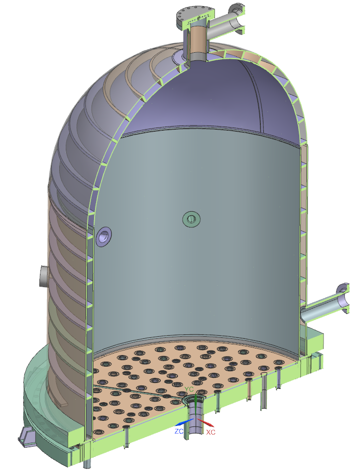
As a Senior Design Engineer, I led the design verification and integrity assessment of multiple critical subassemblies within a Chemical Vapor Deposition (CVD) reactor, deployed in a polysilicon manufacturing plant. The assemblies included the Bell Jar, Baseplate, Jacketed Shell, Nozzles, and Spool Pipes. Due to the reactor’s complex and non-standard geometry, traditional code-based design was insufficient, necessitating advanced Finite Element Analysis (FEA).
SUBASSEMBLIES ANALYZED AND KEY DELIVERABLES:
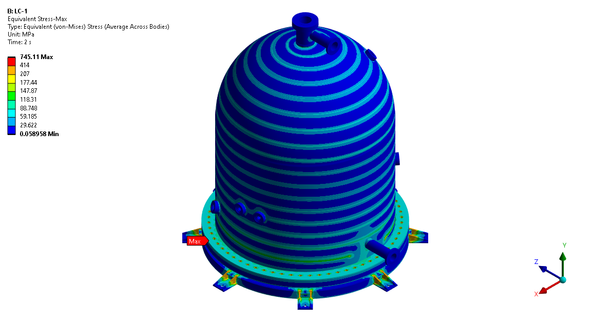
Bell Jar Assembly
Objective:
- Validate structural integrity under internal/external pressure and complex support conditions.
FEA Setup:
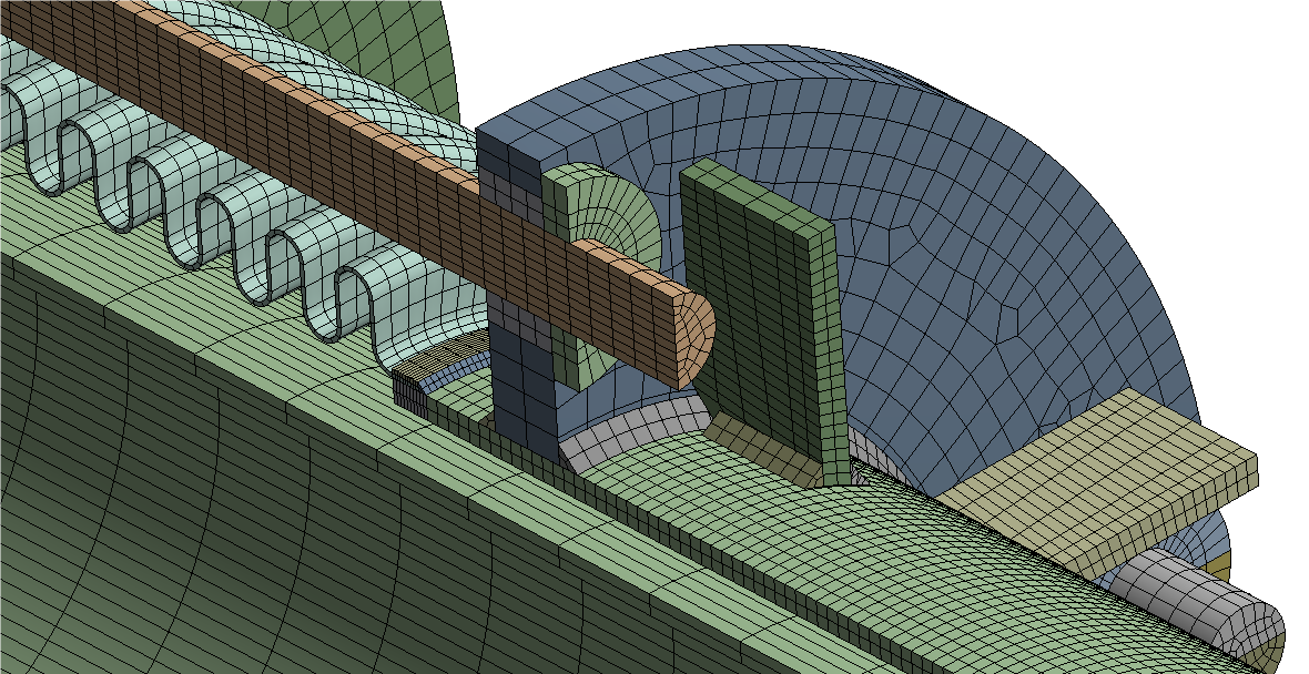
- Meshing: Hex-dominant mesh with local refinement at nozzles and junctions.
- Boundary Conditions: Fixed support at base ring; remote displacement for symmetrical constraints.
- Loading: Included design pressure (internal: 10 bar, external: FV), bolt preload, gravity, and nozzle loads.
Highlights:
- Performed stress linearization at 10+ critical sections to verify primary membrane and bending stresses.
- Buckling analysis confirmed safety margins >1.5 under external pressure loading.
- Seismic loads applied based on IS 1893 Part 4, showing structural stability in modal and response spectrum analysis.
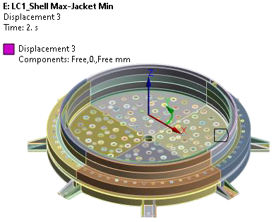
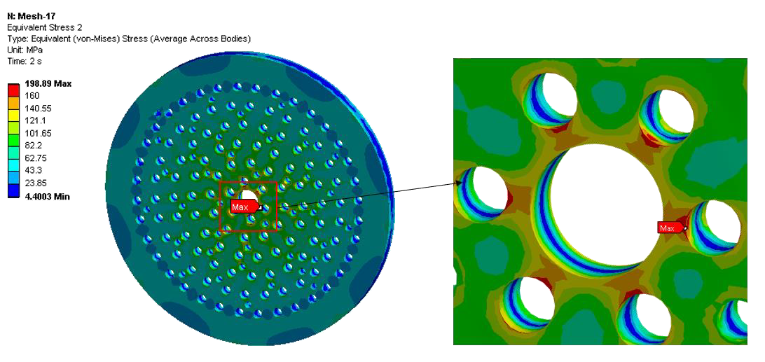
Baseplate and Coverplate
- Challenge: Complex cut-outs and load paths with no standard ASME provisions.
- Approach: FEA-based thickness and junction analysis. Verified weld strength, reinforcement adequacy, and stiffness.
- Notable Detail: Nozzles intersect both plates, requiring load mapping from flanged connections into the shell.
- Boundary Conditions: Fixed base with bolt preload + self-weight + internal pressure distribution.
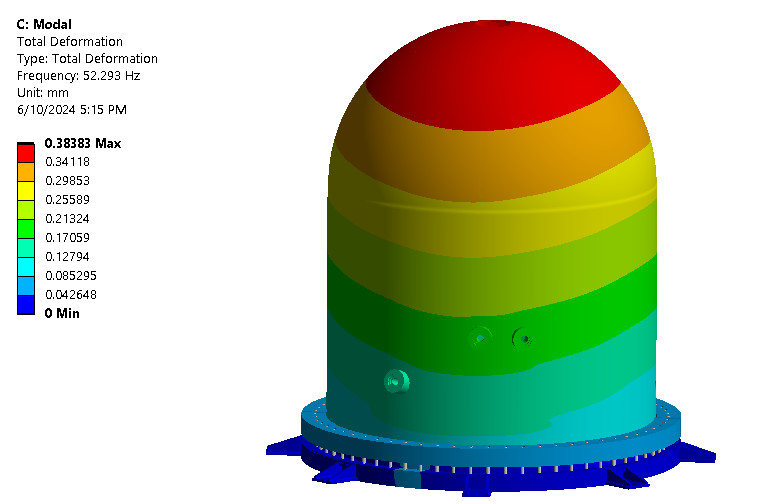
Full Reactor Seismic Assessment
- Scope: Evaluate the complete assembly under seismic events.
- FEA Approach:
- Combined structural model included Bell Jar, Jacket, Nozzles, Lifting Lugs, and Support Lugs.
- Modal analysis identified fundamental frequencies to avoid resonance.
- Loading: Seismic acceleration from IS 1893, bolt pretension, and nozzle weights included.
- Constraints: Baseplate anchored; lateral and vertical constraints applied for realism.
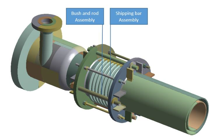
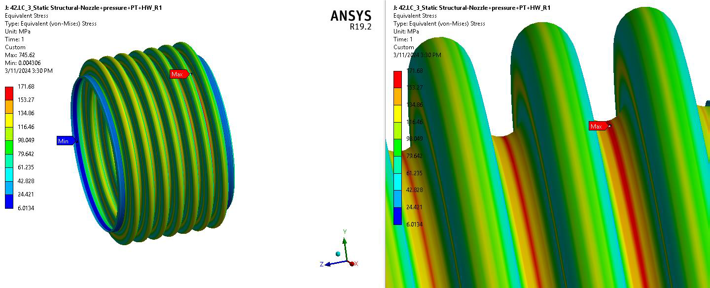
Jacketed Shell & Nozzle Systems
- Analysis: Multi-nozzle verification for both internal/external pressure.
- Complexities:
- Jacketed flanges, pad flanges, and spiral stiffeners not defined in ASME – modeled and validated via FEA.
- WRC 107/297 and WRC 537 used to validate local stress zones.
- Boundary Conditions: Pressure applied to shell/jacket cavities, supports modeled via elastic constraints, bolt connections simulated with pretension forces.
DESIGN CHALLENGES AND RESOLUTIONS:
Challenge 1
Geometry not covered by code Many components (e.g., stub flanges, spiral baffled jackets) had geometries outside ASME Sec. VIII Div. 1. These required justification via FEA under U-2(g) clause.Challenge 2
Combined Loading Conditions Certain parts like Nozzle A and H had to endure multiple simultaneous loads: internal/external pressure, flange bolt loads, and seismic inertia. These were resolved through nonlinear FEA simulations.Challenge 3
Thermal/Pressure Load Coupling Considered gasket behavior, heat expansion mismatch between jacket and shell, and impact of thermal gradients, especially near nozzle junctions.Challenge 4
Buckling and Deformation in Thin Sections Used eigenvalue buckling analysis to validate the safety margins of large-diameter sections under external pressure.TOOLS & TECHNOLOGIES
- FEA Tools: ANSYS Workbench, HYPERMESH
- Design and Modelling: SolidWorks, PV Elite
- Calculations and Documentation: MathCAD, Excel, Word
IMPACT & FUTURE SCOPE
- Delivered fully certified MDRs for each subassembly, including ASME code compliance and client-specific design basis documentation.
- Supported the commissioning of one of India’s first integrated polysilicon production reactors.
- Design successfully passed third-party audits (Worley, Reliance) and field hydrotesting without modifications.